Counter Circuit Diagram Using Flip Flop
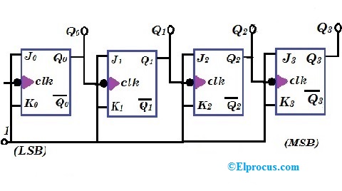
Flip jk flop counter circuit synchronous electronic diagram save flipflop asynchronous bit Counter ripple circuit timing flip bit jk flop diagram using table truth count flops along below diagrams so pulses given 1: a 4 bit ripple counter circuit. the output of one flip-flop clocks
CD4027 JK Flip Flop Pinout, Examples, Working, Datasheet, Applications
Counter synchronous bit down flip jk flop circuit flops count digital tutorial system Digital system tutorial: 3-bit synchronous down counter with jk flip-flops Circuit design of a 4-bit binary counter using d flip-flops – vlsifacts
The 4 bit synchronous up counter circuit constructed with t flip-flops
Counter flip flops vhdl should look may stackCircuit synchronous flip counters flops clock sequential asynchronous circuits electronics inputs Cd4027 jk flip flop pinout, examples, working, datasheet, applicationsCounter synchronous bit binary flip using flops diagram circuit parallel flipflop gates stack count.
Flip-flop circuits : worksheetFlip flop circuits circuit digital flipflop 555 timer frequency voltage worksheets duty potentiometer direction move output would which question follow Binary flops circuitCounter synchronous flops constructed.

Ripple counter
Flip flop proteus pinout datasheet segment numberSynchronous counters Jk flip-flop counter synchronous circuit electronic circuit, pngRipple flop clocks count hence asynchronous counters rantle.
.

Ripple Counter - Circuit Diagram, Timing Diagram, and Applications

Digital System Tutorial: 3-bit Synchronous down counter with JK flip-flops

Circuit Design of a 4-bit Binary Counter Using D Flip-flops – VLSIFacts

Synchronous Counters | Sequential Circuits | Electronics Textbook

flipflop - Parallel binary counter using T flip-flops - Electrical

vhdl - How should a counter with R-S flip-flops look? - Electrical

Flip-flop circuits : Worksheet

1: A 4 bit ripple counter circuit. The output of one flip-flop clocks

CD4027 JK Flip Flop Pinout, Examples, Working, Datasheet, Applications